The use of feedback control to minimize acoustic emissions from an electronic expansion valve
Research sponsored by
Air Conditioning and Refrigeration
Center
University of Illinois at Urbana-Champaign
Department of Mechanical and Industrial Engineering
1206 West Green Street
Urbana, IL 61801
Abstract
Project Objectives
- Develop control strategies to improve the operation of mobile A/C systems (e.g. maximize efficiency, minimize acoustic emissions, improve compressor lubrication, etc.)
- Understand the system mechanics that influence system operation.
- Develop a facility capable of performing experiments that will accurately prove or disprove our hypotheses
Experimental Procedure
Status of refrigerant
- Temperature and Pressure measurements at every non-redundant
point throughout the loop
- Signals from thermocouples and pressure transducers are recorded
and reduced through HP-VEE
Acoustic Emissions (2 ways of estimating noise)
- Accelerometers on tube wall
- Microphone flush to inner tube wall
- Sample at 50kHz
Feedback to Controller
- Temperatures of the refrigerant at inlet and outlet of evaporator
- Thermocouple -> -10 V…+10 V -> ADC
-> controller
 |
Control Objectives
- reduce noise at startup
- reduce compressor wear
- maximize system efficiency
Once the valve is open, and if the system is hot enough, high speed vapor will come whistling through the evaporator. Simply by constricting the flow, it is believed that less noise will be present in the system. This can be accomplished by only opening the EEV some small amount, initially. Once two-phase refrigerant is detected in the lines, the valve can process to a standard control algorithm. Two-phase refrigerant can be detected when the temperature of the refrigerant drops below some known value. This is when the refrigerant has some liquid to vaporize, thus, cooling the refrigerant.
The algorithm will be composed of three distinct modes: a delay mode, an open mode, and a PID mode. The delay mode is when the EEV is fully closed, and the clutch is engaged. This is to reduce the torque on the compressor during startup. Once the delay mode is over, the open mode begins. This is when the EEV opens some predetermined amount. The high-speed refrigerant vapor races through the evaporator, but, hopefully, the noise will be attenuated due to the throttling by the EEV. The open mode will continue until the temperature at the inlet of the evaporator drops below some known value. At this time there is now two-phase refrigerant. Finally, the PID mode is reached. Basically, the DSP will read in the two temperatures, compute the error term, then compute the PID value to be sent to EEV. Of course for the system to work efficiently, the tuning parameters must be correct.
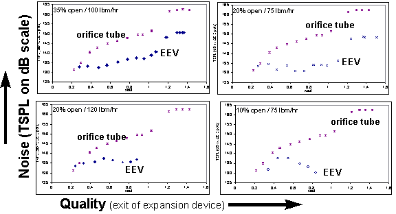
First, a detailed characterization of the acoustic emissions of the
EEV was established. Fig 2 shows how total sound pressure level (a
means to measure acoustic emissions) is related to quality at the exit
of the EEV. Data points for a similar orifice tube were plotted along
with the EEV data as reference. The data reveals that the EEV does
follow similar trends, but it is much quieter.
RESULTS
August 4th, 1998 in Mobil A/C lab
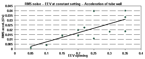
Develop correlation between valve opening and RMS noise
Accelerometer on tube wall to quantify noise

What conditions cause our Sporlan EEV to create noise?
Establish how the EEV should behave.

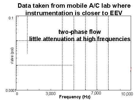
Another finding was that there is less high frequency content
of acoustic emissions in two-phase flow (of refrigerant). The frequency
spectrum seems to “roll off” as the frequency increases. But, this
finding did not agree with data taken in the Mobile A/C Lab. From
the data taken in the Mobile A/C Lab the frequency spectrum of the acoustic
emissions from the EEV during two-phase flow was relatively flat over the
mid to high frequencies. This result contradicted what was expected.
A slight variation in the way data was taken between a previous project
and this project was discovered. The instrumentation (internal microphone)
was closer to the EEV in the Mobile Lab than it was in the previous project's
lab. The following hypothesis was formed: High frequency acoustic
emissions are more easily attenuated in two-phase flow of refrigerant exiting
the expansion valve. The low frequency content is much less attenuated.

TOP OF PAGE | BACK to engineering credentials | BACK to engineering projects | JAMES' HOME
last modified 3 august 2000 send problems and queries to webmaster at: jamessolberg@hotmail.com